- ACCESS EXPO FEATURES
- ACCESS COMPONENTS
- ARCHITECTURES
- SCHEMA ARCHITECTURE
- COMMUNICATION
- Schema communication
- WIRELESS COMMUNICATION
- Wired communication
- Schéma wired
- TITRE SYNOPTIQUE INFRA
- SCHEMA SYNOPTIQUE
ACCESS EXPO FEATURES
ACCESS EXPO is a range of hardware and software solutions, designed to manage electrical distribution at event venues.
The wide range of functions aimed at saving energy, a key issue for all players in the event industry, are at the heart of CSR and sober energy policies.
ACCESS EXPO is a range of hardware and software solutions, designed to manage electrical distribution at event venues.
The wide range of functions aimed at saving energy, a key issue for all players in the event industry, are at the heart of CSR and sober energy policies.
ACCESS EXPO SOFTWARE
The ACCESS software suite offers the main digitalization functionalities, via an application and a back-office.
Various settings can be set, and a simplified operating diagnosis is stored in the ACCESS component.
The ACCESS software suite offers the main digitalization functionalities, via an application and a back-office.
Various settings can be set, and a simplified operating diagnosis is stored in the ACCESS component.
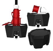
ACCESS EXPO POWER BOXES
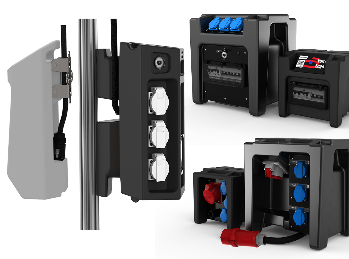
Two ranges and four enclosures of ACCESS by CUBE power distribution boxes, designed to fit in perfectly with all booth configurations and available in a wide range of electrical architectures.
The COMPACT XS© and COMPACT M© boxes are specifically designed for small stands. THE CUBE three-phase boxes are now available in THE CUBE MINI© version, the latest CUBE design innovation.
ACCESS EXPO SPLITTER
The SPLITTER and MULTI PLUG OUTLET accessories are easy to use junction boxes! One SPLITTER, supplied with 32A three-phase power, can supply single-phase power to six COMPACT power distribution boxes.
These are the ideal accessories for saving maximum time when wiring COMPACT and COMPACT XS power distribution boxes.
AT THE CORE OF THE SOLUTION THE ACCESS COMPONENTS
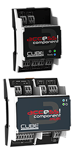
ACCESS consists of a range of electronic components, with one or six outputs, offered on their own or integrated into switchboards of different power ratings, specially designed for the exhibition environment.
ACCESS components and switchboards are intelligent. They are controlled via iOS and Android smartphone applications and via a SaaS backoffice for monitoring and data collection.
ACCESS enables electricians and managers of convention centres and venues to simplify the deployment of power supply, improve quality of service and to optimize the range of services supplies available for exhibitors.
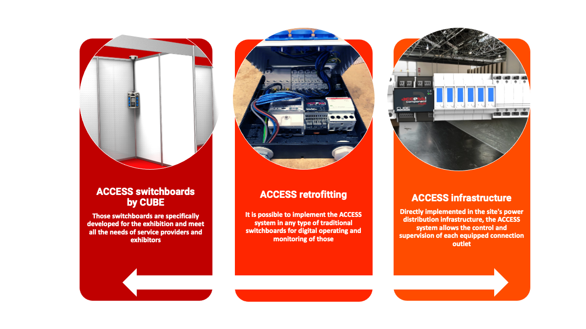
THREE TYPES OF ARCHITECTURES FOR REMOVABLE AND/OR STATIONARY USES
The ACCESS system offers three types of architectures that can be combined, for movable and/or stationary electrical distribution systems.
It consists of an ACCESS 1 OUT or 6 OUT component, combined with a single or three-phase meter (MID) and a switching device (contactor or MN/MX coil).
It consists of an ACCESS 1 OUT or 6 OUT component, combined with a single or three-phase meter (MID) and a switching device (contactor or MN/MX coil).
THREE MODES OF COMMUNICATION
Three modes of communication between ACCESS components and the ACCESS server, hosted in the Cloud, make it possible to deploy the ACCESS solution according to the communication and electrical distribution infrastructure of any venue or congress center.
Three modes of communication between ACCESS components and the ACCESS server, hosted in the Cloud, make it possible to deploy the ACCESS solution according to the communication and electrical distribution infrastructure of any venue or congress center.
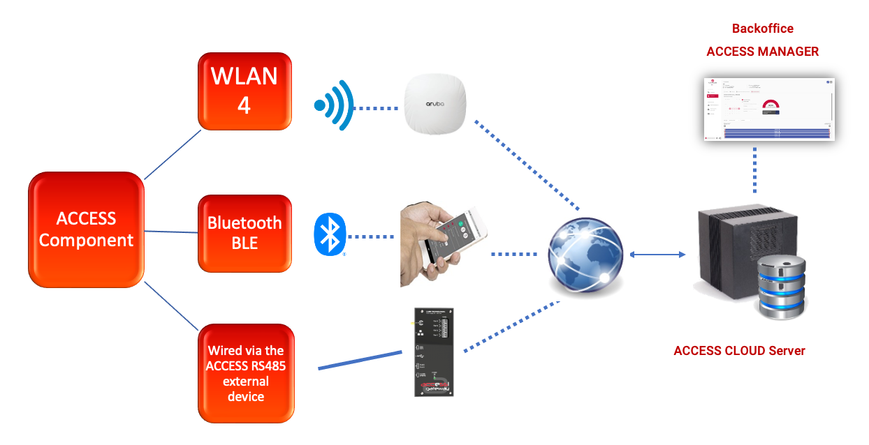
WIRELESS COMMUNICATION MOUVABLE OR STATIONARY DEPLOYMENT
Bluetooth communication
This mode of communication enables autonomous operation and 'proximity' communication, via the ACCESS TECH or ACCESS USER application, independent of the current state of the site's WiFi network. In this case, it is the phone, connected to the Cloud via 4G, 5G or WiFi, that transmits the settings to the component and retrieves the operating data, such as the meter readings and all the status change logs. This mode of operation also means that switchboards equipped with a component can be used at any location.
WLAN communication
The ACCESS component can connect to a site WLAN infrastructure using WiFi 4 (2.4Ghz/WPA2). Communication with the ACCESS Cloud server is initiated by the ACCESS component:
In this case, the ACCESS component communicates with the ACCESS Cloud server at fixed intervals (max.10mn) or when a change of state event occurs (on programming or in the event of overconsumption). It sends its consumption index and the maximum power reached over the last 10 minutes.
The ACCESS component is not programmed in real time from the ACCESS MANAGER back office. The component recovers its new configuration when it connects to the server.
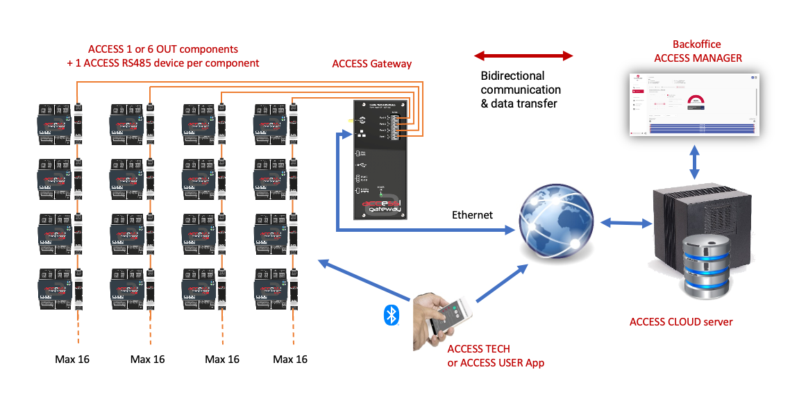
WIRED COMMUNICATION
Wired communication, dedicated to stationary deployment, enables up to 64 RS485 Modules to be connected to the ACCESS Gateway, providing a maximum processing capacity of 384 outputs controlled by 64 ACCESS 6 OUT components.
This fully wired configuration is more secure in an infrastructure environment. It does not require the deployment of a WiFi antenna in the area where the ACCESS components are installed, but only an Internet network link. And of course, the ACCESS TECH application can still be used close to the components.
This fully wired configuration is more secure in an infrastructure environment. It does not require the deployment of a WiFi antenna in the area where the ACCESS components are installed, but only an Internet network link. And of course, the ACCESS TECH application can still be used close to the components.
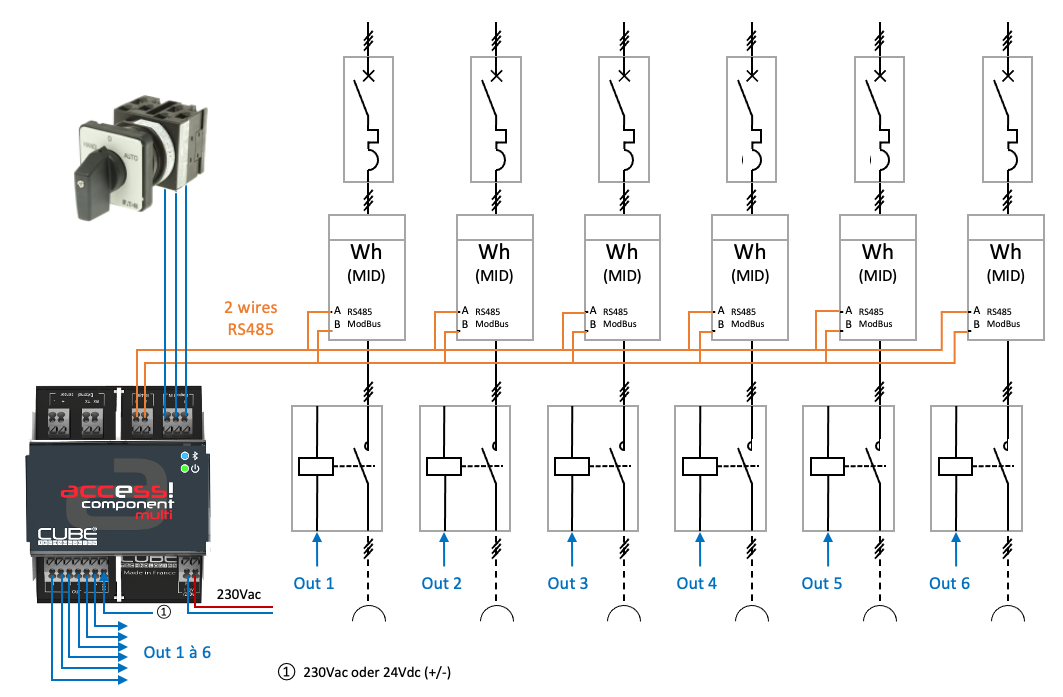
SIMPLIFIED DIAGRAM WIRING OF AN ACCESS 6 OUT COMPONENT
The diagram below illustrates an INFRA deployment:
The ACCESS 6 OUT component drives 6 contactors and is interfaced with 6 counters via its RS485 ModBus bus.
Logic inputs 1&2 can, for example, be connected to a 3-position ON/OFF/AUTO switch.
The ACCESS 6 OUT component drives 6 contactors and is interfaced with 6 counters via its RS485 ModBus bus.
Logic inputs 1&2 can, for example, be connected to a 3-position ON/OFF/AUTO switch.